
Skeleton
At first, a skeleton of two legs, feet and a hip has been build. To allow first movements of the legs, an external control of the robot has been implemented to control the 26 actuators of both legs. The legs, itself, are made of lightweight aluminum just as well as the feet are.
By using the novel actuators, the skeleton design is independent of the actuation of the robot. The arrangement of the points of actuation have more freedom for the new SMA actuator than for rotary electric motors that are placed in the actuated joints in almost all current successfully walking humanoid robots or pneumatic or fluid actuated robotic application like artificial robotic hands. To attach the actuators at the legs, for example, light tension rings are used.
This allows designing the robot without many restrictions, especially, concerning the cover. The different elements of the skeleton are attached with special high performing joints. Other parts of the robot, like the hip, are also made out of aluminum in order to reduce the weight of the robot.
The main interaction of a biped robot with the environment or ground happens with its feet. Human feet have the possibility to work as a damper to compensate small unevenness´s automatically. To reach the same property with the constructed robot, the foot design has to have the possibility of a passive adaptation to the ground.
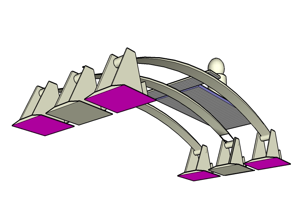
The bioinspired foot design implemented into the robot contains, therefore, three springs. Each spring is fixed at the base plate of the foot and has at the ends brass plates that are able to swivel. A spacer is adjusted between the springs to provide a twisting of them. This design can compensate an unevenness of up to 10mm without a tilt of the plate.
With the help of possible passive adaptation to the ground, the robot maintains balance easier. However, in case of disturbances, the stabilization in general is more difficult.
To actuate the feet, four SMA actuators are placed at them in an angle of 90° to generate motions. A fifth actuator is placed at the back of the foot. This actuator is needed for the robot to be able to tip-toe. This actuator is placed at the center of the back of the feet and supplies in addition a 3.6kg pull force needed for this case.
To connect the upper and lower leg, a steel wire is used as a tendon to overcome the knee-joint. The movement of the lower leg is realized with two actuators, one at the front of the upper leg and one at the back.
The maximum contraction of 8% and the properties of the actuators, avoid the possibility to place actuators with two joints between them. Therefore, the actuators of the upper leg have to be shifted to the upper body to be able to generate more free moving space. The fixing of the four actuators is similar to the fixing of the four actuators at the feet. The point of actuation is next to the hip and the end of the actuation is high in the upper body.
The actuation allows the movement of +/- 45° of the upper legs and feet in two directions and curves the lower leg up to 40° to the back compared to the upper leg at the knee joint.
The next developed step was the construction of the upper body; the head and arms of the robot. The upper body is static and provides space for the microelectronics and batteries. The batteries are placed in the hip and the electronic is placed in the upper body. This leads to a very high center of mass nearly in the middle of the upper body. Caused by this arrangement, each of the legs has a weight of about 1kg only. This allows the legs to swing and reduce the energy consumption, while the robot is able to perform more human-like movements.
Six actuators, that provide three degrees of freedom, actuate each of the two arms. Four actuators are attached to connect the upper arm and the shoulder and two actuators are used for motions of the lower arm.
The head motion and control is realized with two servomotors. One servomotor is used for the azimuth movement of the head, and the other is used for the vertical motions of the head-camera. To be more human-like the robot does not only turn the camera in the head but also the head itself.
The robot has a total height of 130cm. The novel actuator system enables an overall weight of the robot of 6.5kg including electronics and batteries and the outer design covers. Fig 7 shows a photo of the robot. In addition, the contraction of the actuator is noiseless.


CAD Model of Lara´s legs and feet
Fixing of the actuators
Bioinspired Foot Design with force sensors (violett)
Realized feet of Lara
Second CAD Model of Lara including the movement of the actuators
Picture of Lara